IoT Projects & Protocolsbeginnerproject build
5 Practical ESP32 WiFi IoT Projects for Beginners (With Complete Code)
Five beginner ESP32 Wi-Fi projects with full code: web server LED control, temperature logger, MQTT client, relay control and an OLED weather display.
By ADIY12 min read
Technical review pending. Figures marked “verify” or “check your part” have not been confirmed against your exact hardware revision. Check the manufacturer datasheet before relying on them in a design.
1. Introduction: Why ESP32 is the Go-To Chip for IoT in India#
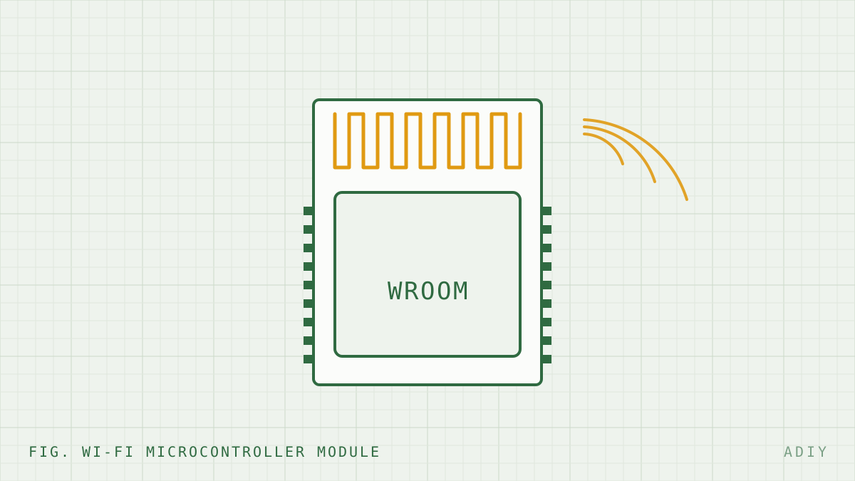
If you are looking to build connected devices, smart home automation systems, or remote sensor networks, the ESP32 WiFi project ecosystem is where you should begin. The ESP32, developed by Espressif Systems, is a powerful, low-cost micro-controller featuring built-in Wi-Fi and dual-mode Bluetooth.
For makers, students, and professional engineers executing ESP32 projects in India, this microcontroller offers unparalleled value. It provides far more processing power (typically a dual-core 160MHz to 240MHz CPU) than a standard Arduino Uno, more RAM, and native wireless capabilities—all for just a few hundred rupees.
In this comprehensive ESP32 IoT tutorial, we will walk you through 5 practical, hands-on projects. We have designed these projects specifically for beginners, complete with exact wiring tables and fully tested Arduino IDE code. By the end of this guide, you will be able to control appliances via web browsers, log sensor data, and communicate with IoT platforms using MQTT.
2. What You Need (Components List)#
To follow along with all five projects in this tutorial, you will need the following components. We proudly design and manufacture reliable development boards and modules under the 'Make in India' initiative at ADIY.
- Development Board: Any standard ESP32 Development Board (like the ESP32 NodeMCU 38-pin or 30-pin variant).
- Sensors: DHT22 Temperature and Humidity Sensor. (Browse ADIY Sensors)
- Actuators: 5V Single Channel or Dual Channel Relay Module. (Browse ADIY Relay Boards)
- Display: 0.96 inch I2C OLED Display (SSD1306).
- Basics: Breadboard, jumper wires (Male-to-Male, Male-to-Female), LEDs, and 220-ohm resistors.
3. Setting Up ESP32 in Arduino IDE#
Before writing our first line of code, we need to prepare the Arduino IDE to communicate with the ESP32.
- Open Arduino IDE. Go to File > Preferences.
- In the "Additional Boards Manager URLs" field, paste the following URL:
https://raw.githubusercontent.com/espressif/arduino-esp32/gh-pages/package_esp32_index.json - Click OK. Then navigate to Tools > Board > Boards Manager.
- Search for "esp32" and install the package by Espressif Systems.
- Once installed, select your specific board from Tools > Board > ESP32 Arduino (e.g., "DOIT ESP32 DEVKIT V1").
- Select the correct COM port under Tools > Port.
4. Project 1: ESP32 Web Server — Control LED via Browser#
Our first ESP32 WiFi project is a classic IoT milestone: building a standalone web server. The ESP32 will host a simple HTML webpage. When you access this page using your smartphone or laptop (connected to the same WiFi network), you can click buttons to turn an LED on or off.
Wiring the LED#
| ESP32 Pin | Component Connection |
|---|---|
| GPIO 2 (or built-in LED) | LED Anode (Long leg) |
| GND | LED Cathode (Short leg) via 220Ω resistor |
Arduino Code#
Copy and paste this code, remembering to change "YOUR_SSID" and "YOUR_PASSWORD" to your actual WiFi credentials.
#include <WiFi.h>
const char* ssid     = "YOUR_SSID";
const char* password = "YOUR_PASSWORD";
WiFiServer server(80);
const int ledPin = 2; // GPIO 2 (Often the built-in LED)
String header;
void setup() {
  Serial.begin(115200);
  pinMode(ledPin, OUTPUT);
  digitalWrite(ledPin, LOW);
  // Connect to Wi-Fi network
  Serial.print("Connecting to ");
  Serial.println(ssid);
  WiFi.begin(ssid, password);
  while (WiFi.status() != WL_CONNECTED) {
    delay(500);
    Serial.print(".");
  }
  Serial.println("");
  Serial.println("WiFi connected.");
  Serial.println("IP address: ");
  Serial.println(WiFi.localIP());
  server.begin();
}
void loop() {
  WiFiClient client = server.available(); // Listen for incoming clients
  if (client) {
    String currentLine = "";
    while (client.connected()) {
      if (client.available()) {
        char c = client.read();
        header += c;
        if (c == '\n') {
          // End of HTTP request
          if (currentLine.length() == 0) {
            // Send HTTP headers
            client.println("HTTP/1.1 200 OK");
            client.println("Content-type:text/html");
            client.println("Connection: close");
            client.println();

            // Turn LED on/off based on URL
            if (header.indexOf("GET /2/on") >= 0) {
              digitalWrite(ledPin, HIGH);
            } else if (header.indexOf("GET /2/off") >= 0) {
              digitalWrite(ledPin, LOW);
            }

            // Display HTML web page
            client.println("<!DOCTYPE html><html>");
            client.println("<head><meta name=\"viewport\" content=\"width=device-width, initial-scale=1\">");
            client.println("<style>body { text-align: center; font-family: Arial;}");
            client.println(".button { background-color: #83B735; border: none; color: white; padding: 16px 40px;");
            client.println("text-decoration: none; font-size: 30px; margin: 2px; cursor: pointer; border-radius: 8px;}");
            client.println(".button2 {background-color: #555555;}</style></head>");
            client.println("<body><h1>ADIY ESP32 Web Server</h1>");

            client.println("<p><a href=\"/2/on\"><button class=\"button\">ON</button></a></p>");
            client.println("<p><a href=\"/2/off\"><button class=\"button button2\">OFF</button></a></p>");
            client.println("</body></html>");
            client.println();
            break;
          } else {
            currentLine = "";
          }
        } else if (c != '\r') {
          currentLine += c;
        }
      }
    }
    header = "";
    client.stop();
  }
}
How to test: Open the Serial Monitor at 115200 baud. Press the EN (reset) button on the ESP32. Wait for it to connect to WiFi and note the IP address printed (e.g., 192.168.1.15). Open a browser on your phone, type that IP address, and tap the buttons to control the LED!
5. Project 2: ESP32 WiFi Temperature Logger with DHT22#
Environmental monitoring is a cornerstone of IoT. In this project, we'll read data from a DHT22 temperature and humidity sensor. We will configure the ESP32 to connect to WiFi and we can print the formatted data to the Serial Monitor, laying the groundwork for sending it to a cloud dashboard.
Wiring the DHT22#
| DHT22 Pin | ESP32 Connection |
|---|---|
| VCC (Pin 1) | 3V3 |
| DATA (Pin 2) | GPIO 4 |
| GND (Pin 4) | GND |
Note: Place a 10kΩ pull-up resistor between VCC and DATA if your DHT22 module does not already have one built-in.
Arduino Code#
You will need to install the DHT sensor library by Adafruit via the Library Manager (Sketch > Include Library > Manage Libraries).
#include <WiFi.h>
#include "DHT.h"
#define DHTPIN 4
#define DHTTYPE DHT22
DHT dht(DHTPIN, DHTTYPE);
const char* ssid = "YOUR_SSID";
const char* password = "YOUR_PASSWORD";
void setup() {
  Serial.begin(115200);
  dht.begin();

  WiFi.begin(ssid, password);
  Serial.print("Connecting to WiFi");
  while (WiFi.status() != WL_CONNECTED) {
    delay(500);
    Serial.print(".");
  }
  Serial.println("\nConnected to WiFi!");
}
void loop() {
  delay(2000); // DHT22 requires 2 seconds between readings
  float h = dht.readHumidity();
  float t = dht.readTemperature();
  if (isnan(h) || isnan(t)) {
    Serial.println("Failed to read from DHT sensor!");
    return;
  }
  // Format data for potential cloud transmission
  String dataString = "{\"temperature\": " + String(t) + ", \"humidity\": " + String(h) + "}";

  Serial.print("Sensor Data: ");
  Serial.println(dataString);
}
6. Project 3: ESP32 MQTT Client (Publish Sensor Data)#
HTTP web servers are great, but MQTT (Message Queuing Telemetry Transport) is the true standard protocol for IoT. It is lightweight and perfect for microcontrollers. In this ESP32 IoT tutorial step, we will make our ESP32 act as an MQTT client that publishes a simple message to a public Mosquitto broker.
Arduino Code#
Install the PubSubClient library by Nick O'Leary via the Library Manager before uploading this code.
#include <WiFi.h>
#include <PubSubClient.h>
const char* ssid = "YOUR_SSID";
const char* password = "YOUR_PASSWORD";
// Public Mosquitto Broker
const char* mqtt_server = "test.mosquitto.org";
WiFiClient espClient;
PubSubClient client(espClient);
void setup_wifi() {
  delay(10);
  Serial.println();
  Serial.print("Connecting to ");
  Serial.println(ssid);
  WiFi.begin(ssid, password);
  while (WiFi.status() != WL_CONNECTED) {
    delay(500);
    Serial.print(".");
  }
  Serial.println("");
  Serial.println("WiFi connected");
}
void reconnect() {
  while (!client.connected()) {
    Serial.print("Attempting MQTT connection...");
    // Create a random client ID
    String clientId = "ESP32Client-";
    clientId += String(random(0xffff), HEX);

    if (client.connect(clientId.c_str())) {
      Serial.println("connected");
    } else {
      Serial.print("failed, rc=");
      Serial.print(client.state());
      Serial.println(" try again in 5 seconds");
      delay(5000);
    }
  }
}
void setup() {
  Serial.begin(115200);
  setup_wifi();
  client.setServer(mqtt_server, 1883);
}
void loop() {
  if (!client.connected()) {
    reconnect();
  }
  client.loop();
  // Publish a message every 5 seconds
  static unsigned long lastMsg = 0;
  unsigned long now = millis();
  if (now - lastMsg > 5000) {
    lastMsg = now;
    String payload = "Hello from ADIY ESP32! Uptime: " + String(now/1000) + "s";
    Serial.print("Publishing message: ");
    Serial.println(payload);

    // Publish to a unique topic
    client.publish("adiy/test/esp32", payload.c_str());
  }
}
7. Project 4: ESP32 Remote Relay Control#
Controlling an LED is fun, but true home automation requires controlling high-voltage appliances. We achieve this using a Relay Module. Building upon Project 1, we will replace the LED with a relay to switch a device on/off over WiFi.
Wiring the Relay#
| Relay Module Pin | ESP32 Connection |
|---|---|
| VCC | VIN / 5V (ESP32 must be powered by USB for 5V out) |
| GND | GND |
| IN (Signal) | GPIO 26 |
For the code, you can use the exact same code from Project 1, but change the ledPin variable to 26. Ensure you understand if your relay is Active HIGH or Active LOW. Many 5V relays are active LOW, meaning digitalWrite(relayPin, LOW) turns the appliance ON.
For a deeper dive into home automation concepts using relays, check out our related article: Home Automation with Relay Modules.
8. Project 5: ESP32 Weather Display (DHT22 + OLED SSD1306)#
Let's combine sensors and displays. In this project, we'll read the DHT22 and display the current temperature and humidity on a crisp 0.96" I2C OLED display. While this doesn't strictly use WiFi, it's a foundational UI block for any ESP32 IoT project—you can easily add WiFi to fetch and display internet weather data!
Wiring#
Keep the DHT22 wired to GPIO 4. Add the OLED display using the ESP32's default I2C pins:
| OLED Pin | ESP32 Connection |
|---|---|
| VCC | 3V3 |
| GND | GND |
| SCL | GPIO 22 |
| SDA | GPIO 21 |
Arduino Code#
Install the Adafruit SSD1306 and Adafruit GFX Library.
#include <Wire.h>
#include <Adafruit_GFX.h>
#include <Adafruit_SSD1306.h>
#include "DHT.h"
#define SCREEN_WIDTH 128
#define SCREEN_HEIGHT 64
#define OLED_RESET    -1
Adafruit_SSD1306 display(SCREEN_WIDTH, SCREEN_HEIGHT, &Wire, OLED_RESET);
#define DHTPIN 4
#define DHTTYPE DHT22
DHT dht(DHTPIN, DHTTYPE);
void setup() {
  Serial.begin(115200);
  dht.begin();
  if(!display.begin(SSD1306_SWITCHCAPVCC, 0x3C)) {
    Serial.println(F("SSD1306 allocation failed"));
    for(;;);
  }
  display.clearDisplay();
  display.setTextColor(WHITE);
}
void loop() {
  delay(2000);
  float h = dht.readHumidity();
  float t = dht.readTemperature();
  display.clearDisplay();

  if (isnan(h) || isnan(t)) {
    display.setCursor(0, 10);
    display.setTextSize(1);
    display.print("Sensor Error!");
    display.display();
    return;
  }
  // Display Temperature
  display.setTextSize(1);
  display.setCursor(0, 0);
  display.print("Temperature:");
  display.setTextSize(2);
  display.setCursor(0, 15);
  display.print(t);
  display.print(" C");
  // Display Humidity
  display.setTextSize(1);
  display.setCursor(0, 40);
  display.print("Humidity:");
  display.setTextSize(2);
  display.setCursor(0, 50);
  display.print(h);
  display.print(" %");
  display.display();
}
If you enjoy environmental monitoring, take it a step further with our guide on building an IoT Weather Station using ESP32 and BME280.
9. Troubleshooting ESP32 WiFi Issues#
Working on an ESP32 WiFi project isn't always perfectly smooth. Here are the 5 most common issues beginners face and how to solve them:
- "Connecting........" Loop: The ESP32 only supports 2.4GHz WiFi. If your router is heavily steering devices to 5GHz, or if you provided the SSID of a 5GHz-only network, the ESP32 will never connect. Ensure your 2.4GHz band is active.
- Brownout Detector Triggered: If your Serial Monitor repeatedly prints "Brownout detector was triggered", the ESP32 isn't getting enough current. The WiFi radio consumes a spike of power (up to ~250mA-300mA) when turning on. Use a better quality USB cable or an external 5V power supply.
- Fatal Error: Failed to connect to ESP32: This happens during upload. The IDE can't initiate programming mode. Hold down the "BOOT" button on the board as soon as you see "Connecting..." in the IDE console.
- IP Address returns 0.0.0.0: This indicates the WiFi connection failed but the code proceeded anyway. Ensure your
WiFi.status() == WL_CONNECTEDwhile loop is properly holding the code execution until connection is achieved. - MQTT Connection Refused: If the WiFi connects but MQTT fails, verify the broker URL, ensure port 1883 is open on your network, and crucially, ensure your MQTT Client ID is unique (which is why we added a random hex string in Project 3).
10. Next Steps & FAQ#
Congratulations! You have successfully navigated the basics of ESP32 IoT development. From local web servers to global MQTT messaging, you now possess the foundational skills to build complex smart devices.
To continue your journey, consider exploring Arduino Compatible boards for simpler non-WiFi projects, or dive deeper into custom PCB design. Explore our full range of Arduino Compatible boards for your next prototype.
Why is my ESP32 not connecting to WiFi?
The ESP32 only supports 2.4GHz WiFi networks. Ensure your router is broadcasting a 2.4GHz signal and that you have entered the correct SSID and password. Also, check your power supply, as the ESP32 needs adequate current during WiFi transmission.
Can I power an ESP32 with a 9V battery?
No, the ESP32 operates at 3.3V. While many development boards have onboard voltage regulators (like the AMS1117) that accept 5V via USB or VIN, connecting a 9V battery directly can overheat the regulator or damage the board. Use a proper 5V source or a step-down converter.
Which pins are safe to use on the ESP32?
Pins 6-11 are connected to the internal flash memory and should be avoided. Pins 34, 35, 36, and 39 are input-only and do not have internal pull-up/pull-down resistors. Generally, pins like 2, 4, 12-19, 21-23, 25-27, 32, and 33 are safe to use for most input/output operations.
How do I fix 'Brownout detector was triggered' error?
This error occurs when the ESP32 does not receive enough power (voltage drops below a certain threshold), often during WiFi initialization. Ensure you are using a good quality USB cable and a power supply capable of delivering at least 500mA (preferably 1A or more).
Share