Motors & Roboticsbeginneradiy labs
L298N Motor Driver Module: Complete Guide with Arduino Wiring & Code
L298N motor driver with Arduino: H-bridge basics, PWM speed control, direction control, stepper driving, wiring diagrams and working code.
By ADIY12 min read
Technical review pending. Figures marked “verify” or “check your part” have not been confirmed against your exact hardware revision. Check the manufacturer datasheet before relying on them in a design.
1. Introduction — Motor Control Fundamentals#
If you're building a robot, a smart car, or any mechanical project, getting your motors to spin exactly the way you want is crucial. Standard microcontrollers like an Arduino or ESP32 are fantastic for processing logic, but their output pins simply can't provide enough current (typically limited to 20-40mA) to drive DC motors directly. Attempting to do so can fry your beloved development board.
This is where motor drivers step in. Motor drivers act as amplifiers. They take the low-current control signals from your microcontroller and convert them into higher-current signals capable of driving mechanical loads. Among the most popular, cost-effective, and robust drivers in the Maker community is the L298N Motor Driver Module.
In this guide, the ADIY Engineering Team breaks down everything you need to know about using the L298N motor driver Arduino combination. From basic wiring to advanced PWM speed control and stepper driving, you'll find real-world code and practical insights suited for developers and hobbyists across India and beyond.
2. L298N Module Overview & Specifications#
The L298N module is built around the L298 dual H-bridge motor driver chip. It’s highly versatile, capable of driving two DC motors independently or a single 2-phase bipolar stepper motor. The large heatsink attached to the IC is necessary because linear regulators and BJT (Bipolar Junction Transistor) based H-bridges dissipate a fair amount of heat during operation.
Key Specifications#
- Motor Power Supply (Vs): 5V to 35V
- Logic Power Supply (Vss): 5V to 7V (usually powered via the onboard 5V regulator)
- Continuous Current: 2A per channel (peaks up to 3A max)
- Logic Current: 0mA to 36mA
- Maximum Power Dissipation: 25W (with heatsink)
- Control Interface: Standard 5V TTL logic (perfect for ADIY UNO R3)
3. Pin Description Table#
Understanding the pins on the L298N is the first step to successful wiring. The module features screw terminals for power and motors, and standard male header pins for logic input.
| Pin Name | Type | Description |
|---|---|---|
| 12V (VCC) | Power In | Main motor power supply. Connect your battery here (5V to 35V). |
| GND | Ground | System Ground. Must be connected to Arduino GND. |
| 5V | Power Out/In | Outputs 5V if the onboard regulator jumper is on (supply max 12V). If supply >12V, remove jumper and supply 5V here to power logic. |
| ENA | Input | Enable for Motor A. Use PWM for speed control. Jumper to 5V for full speed. |
| IN1 & IN2 | Input | Logic inputs for Motor A direction control. |
| IN3 & IN4 | Input | Logic inputs for Motor B direction control. |
| ENB | Input | Enable for Motor B. Use PWM for speed control. Jumper to 5V for full speed. |
| OUT1 & OUT2 | Output | Connections for DC Motor A. |
| OUT3 & OUT4 | Output | Connections for DC Motor B. |
4. H-Bridge Theory#
How does the L298N reverse the direction of a DC motor without manually swapping the wires? The answer lies in the "H-Bridge" circuit.
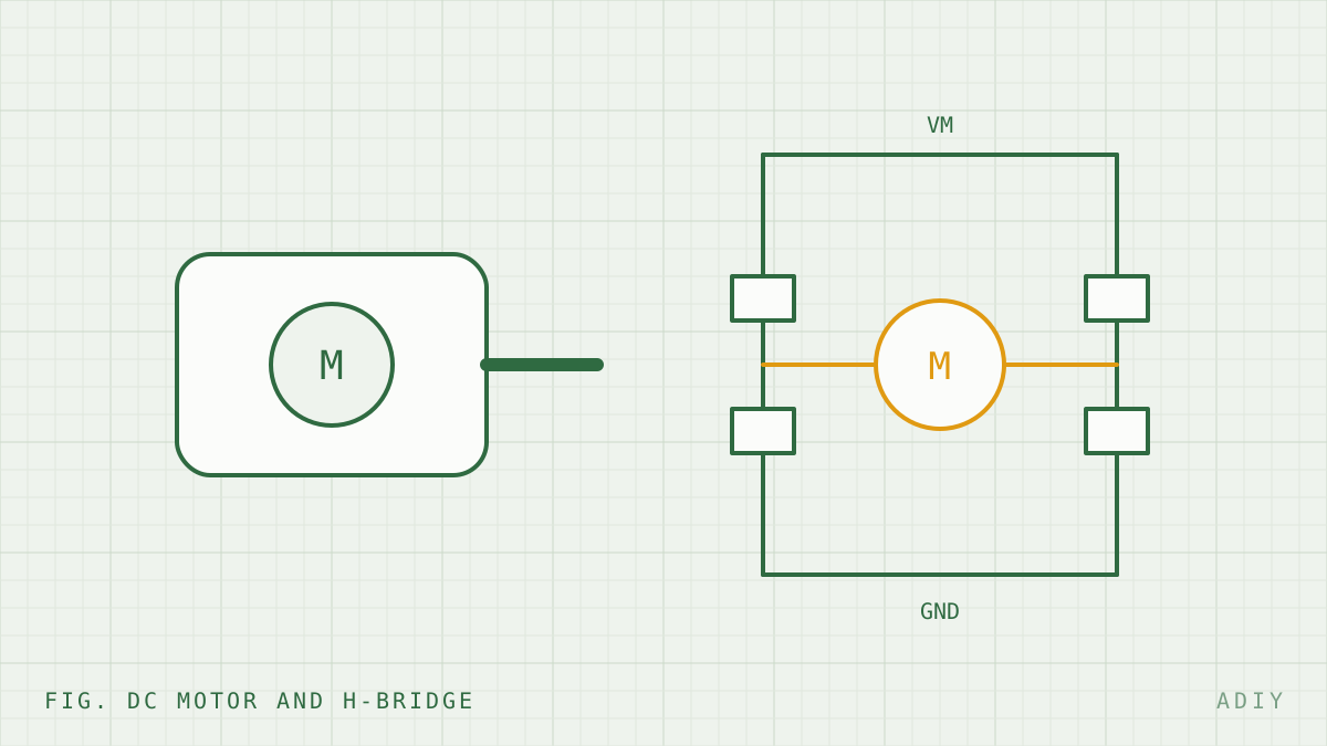
An H-bridge is a circuit consisting of four electronic switches (transistors or MOSFETs) arranged in the shape of an 'H' with the motor in the center. By selectively closing pairs of switches, you dictate the path of the current through the motor.
- Forward: Switches 1 and 4 are closed; current flows left to right. Motor spins forward.
- Reverse: Switches 2 and 3 are closed; current flows right to left. Motor spins in reverse.
- Stop (Brake): Switches 1 and 3 (or 2 and 4) are closed. The motor terminals are shorted together, causing a dynamic braking effect.
The L298N houses two of these H-bridge circuits, allowing independent control of two DC motors.
5. Logic Table#
To control the switches in the H-bridge, we apply HIGH (5V) or LOW (0V) signals to the IN pins. Here is the control logic for Motor A (IN1/IN2). Motor B (IN3/IN4) behaves identically.
| ENA | IN1 | IN2 | Motor A Status |
|---|---|---|---|
| HIGH (or PWM) | HIGH | LOW | Forward |
| HIGH (or PWM) | LOW | HIGH | Reverse |
| HIGH (or PWM) | HIGH | HIGH | Stop / Fast Motor Brake |
| HIGH (or PWM) | LOW | LOW | Stop / Coasting |
| LOW | X (Any) | X (Any) | Off (No Power) |
6. Wiring: Two DC Motors with ADIY UNO R3#
Let's wire up a classic 2-wheel drive robot chassis. We will use an ADIY UNO R3, the L298N, two standard yellow gear motors, and a 9V battery for the motors.
| ADIY UNO R3 Pin | L298N Module Pin | External Power / Motors |
|---|---|---|
| Digital 9 (PWM) | ENA (Remove Jumper) | - |
| Digital 8 | IN1 | - |
| Digital 7 | IN2 | - |
| Digital 5 | IN3 | - |
| Digital 4 | IN4 | - |
| Digital 10 (PWM) | ENB (Remove Jumper) | - |
| GND | GND | Battery Negative (-) |
| - | 12V Terminal | Battery Positive (+) e.g., 9V or 12V |
| - | OUT1 & OUT2 | Motor A Wires |
| - | OUT3 & OUT4 | Motor B Wires |
7. Code 1: Basic Forward/Reverse/Stop Control#
This foundational sketch sets up the pins and drives the motors forward for 2 seconds, reverses them for 2 seconds, and stops. Note that since we aren't using PWM yet, ENA and ENB should be held HIGH (you can write them HIGH in code, or leave the physical jumpers on if you don't connect wires to pins 9 and 10).
// ADIY Motor Control - Basic Forward/Reverse
// Motor A
const int enA = 9;
const int in1 = 8;
const int in2 = 7;
// Motor B
const int enB = 10;
const int in3 = 5;
const int in4 = 4;
void setup() {
  // Set all motor control pins to outputs
  pinMode(enA, OUTPUT);
  pinMode(enB, OUTPUT);
  pinMode(in1, OUTPUT);
  pinMode(in2, OUTPUT);
  pinMode(in3, OUTPUT);
  pinMode(in4, OUTPUT);

  // Turn on motors (Maximum speed)
  digitalWrite(enA, HIGH);
  digitalWrite(enB, HIGH);
}
void loop() {
  // Move Forward
  digitalWrite(in1, HIGH);
  digitalWrite(in2, LOW);
  digitalWrite(in3, HIGH);
  digitalWrite(in4, LOW);
  delay(2000); // Run for 2 seconds
  // Move Reverse
  digitalWrite(in1, LOW);
  digitalWrite(in2, HIGH);
  digitalWrite(in3, LOW);
  digitalWrite(in4, HIGH);
  delay(2000); // Run for 2 seconds
  // Stop Motors
  digitalWrite(in1, LOW);
  digitalWrite(in2, LOW);
  digitalWrite(in3, LOW);
  digitalWrite(in4, LOW);
  delay(2000); // Stop for 2 seconds
}
8. Code 2: PWM Speed Control#
Moving at 100% speed all the time is rarely ideal. To control speed, we use Pulse Width Modulation (PWM) on the ENA and ENB pins. The analogWrite() function takes a value from 0 (stopped) to 255 (full speed).
// ADIY Motor Control - PWM Speed Control
const int enA = 9;
const int in1 = 8;
const int in2 = 7;
const int enB = 10;
const int in3 = 5;
const int in4 = 4;
void setup() {
  pinMode(enA, OUTPUT);
  pinMode(enB, OUTPUT);
  pinMode(in1, OUTPUT);
  pinMode(in2, OUTPUT);
  pinMode(in3, OUTPUT);
  pinMode(in4, OUTPUT);

  // Set direction to Forward
  digitalWrite(in1, HIGH);
  digitalWrite(in2, LOW);
  digitalWrite(in3, HIGH);
  digitalWrite(in4, LOW);
}
void loop() {
  // Accelerate from zero to maximum speed
  for (int speed = 0; speed <= 255; speed++) {
    analogWrite(enA, speed);
    analogWrite(enB, speed);
    delay(20);
  }

  // Decelerate from maximum speed to zero
  for (int speed = 255; speed >= 0; speed--) {
    analogWrite(enA, speed);
    analogWrite(enB, speed);
    delay(20);
  }
}
9. Code 3: Automatic Direction Reversal (Timer-Based)#
Often, you want functions to handle your driving logic. This code demonstrates how to create reusable functions for driving and automatically reversing direction.
// ADIY Motor Control - Auto Reversal
const int enA = 9, in1 = 8, in2 = 7;
const int enB = 10, in3 = 5, in4 = 4;
void setup() {
  pinMode(enA, OUTPUT); pinMode(enB, OUTPUT);
  pinMode(in1, OUTPUT); pinMode(in2, OUTPUT);
  pinMode(in3, OUTPUT); pinMode(in4, OUTPUT);
}
void drive(int speed, bool forward) {
  analogWrite(enA, speed);
  analogWrite(enB, speed);

  if (forward) {
    digitalWrite(in1, HIGH); digitalWrite(in2, LOW);
    digitalWrite(in3, HIGH); digitalWrite(in4, LOW);
  } else {
    digitalWrite(in1, LOW); digitalWrite(in2, HIGH);
    digitalWrite(in3, LOW); digitalWrite(in4, HIGH);
  }
}
void brake() {
  digitalWrite(in1, LOW); digitalWrite(in2, LOW);
  digitalWrite(in3, LOW); digitalWrite(in4, LOW);
  analogWrite(enA, 0); analogWrite(enB, 0);
}
void loop() {
  drive(200, true);  // Drive forward at speed 200
  delay(3000);
  brake();
  delay(1000);
  drive(150, false); // Reverse slower at speed 150
  delay(3000);
  brake();
  delay(1000);
}
10. Wiring Stepper Motor with L298N#
The L298N isn't just for DC motors; it can drive a single bipolar stepper motor (like a NEMA 17) very effectively. Stepper motors have two coils. We connect Coil A to OUT1/OUT2, and Coil B to OUT3/OUT4.
- NEMA 17 A+ (Black) to OUT1
- NEMA 17 A- (Green) to OUT2
- NEMA 17 B+ (Red) to OUT3
- NEMA 17 B- (Blue) to OUT4
Note: Wire colors can vary by manufacturer. Always use a multimeter to check continuity across pairs to find the coils.
Keep the ENA and ENB jumpers ON (connected to 5V) for stepper driving, as we need constant max logic voltage for stepping sequences.
11. Code 4: Stepper Motor Control (Full-Step)#
To use a stepper, the easiest method is to use the built-in Arduino Stepper.h library.
// ADIY Stepper Control using L298N
#include
const int stepsPerRevolution = 200;  // 1.8 degree per step for NEMA 17
// Initialize the stepper library on pins 8 through 11:
// Note the sequence: IN1, IN3, IN2, IN4
Stepper myStepper(stepsPerRevolution, 8, 10, 9, 11);
void setup() {
  // set the speed at 60 rpm:
  myStepper.setSpeed(60);
  Serial.begin(9600);
}
void loop() {
  // step one revolution in one direction:
  Serial.println("clockwise");
  myStepper.step(stepsPerRevolution);
  delay(500);
  // step one revolution in the other direction:
  Serial.println("counterclockwise");
  myStepper.step(-stepsPerRevolution);
  delay(500);
}
12. External Power Supply Notes#
A frequent mistake beginners make is trying to power DC motors directly from the Arduino's 5V pin. Do not do this. Motors draw a lot of current (often >500mA under load), which will burn out the Arduino’s voltage regulator.
Instead, use an external power source (like a 2S/3S LiPo battery, or a battery holder with 6xAA batteries). Connect the positive to the L298N's 12V terminal, and the negative to the GND terminal. From the L298N's 5V terminal, you can then safely power your Arduino by connecting it to the Arduino's 5V or VIN pin (ensure the 5V jumper on the L298N is closed).
13. Troubleshooting (5 Common Issues)#
- Motor doesn't move, but LED is on: You likely forgot to connect the ground of your battery to the ground of the Arduino. Common grounds are essential!
- Motor spins the wrong direction: Simply swap the two wires connected to the OUT terminal for that specific motor, or change the HIGH/LOW logic in your code.
- L298N heatsink gets very hot: The L298N has a voltage drop of about ~2V, which is dissipated as heat. If it gets burning hot, your motor is drawing too much current (>2A). You may need a higher-rated driver like the BTS7960.
- PWM speed control isn't working: Ensure you removed the ENA/ENB jumpers. Also, check that you are connected to a PWM-capable pin on the Arduino (marked with a ~ symbol, like 3, 5, 6, 9, 10, 11).
- Power cuts out when motors start: Your battery cannot supply enough current, causing voltage sag that resets the Arduino. Use a higher C-rating battery (like LiPo) or ensure separate power supplies.
14. FAQ#
Why is my motor not running even when connected to the L298N?
Check if your power supply is adequate. The Arduino's 5V pin cannot provide enough current for most motors. Use an external battery (e.g., 9V or 12V) connected to the L298N's 12V terminal, and ensure all grounds are connected together.
Do I need to remove the jumper on ENA/ENB for PWM speed control?
Yes! To control motor speed, you must remove the jumpers on the ENA and ENB pins and connect them to PWM-capable pins on your Arduino (like D5, D6, D9, D10, D11).
Can the L298N drive a NEMA 17 stepper motor?
Yes, it can drive smaller bipolar stepper motors like the NEMA 17, as long as the current draw per phase doesn't exceed 2A. However, dedicated stepper drivers (like A4988) are better for precise microstepping.
What is the 5V jumper on the L298N used for?
The 5V jumper enables the onboard 5V voltage regulator. If your motor power supply is between 7V and 12V, leave it ON. If your supply is greater than 12V, remove the jumper to prevent the regulator from burning out, and supply an external 5V to the 5V pin.
Products & resources
Arduino Compatible
UNO R3 Beginner kit – ADIY
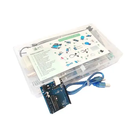
ADIY Uno R3 Beginners Kit is a Stepping Stone for beginners who want to learn about electronic sensors and are excited to make projects. Beginners can learn the basics of UNO programming. Great for Starting with Arduino…
₹1,469
Datasheet
Share