Motors & Roboticsbeginneradiy labs
Servo Motors SG90 & MG996R: Working Principle, Wiring & Arduino Control Guide
How servo motors work and how to wire and control the SG90 and MG996R with Arduino, including power supply tips and example sketches.
By ADIY11 min read
Technical review pending. Figures marked “verify” or “check your part” have not been confirmed against your exact hardware revision. Check the manufacturer datasheet before relying on them in a design.
1. Introduction: What is a Servo Motor?#
Welcome to the ultimate guide to servo motor Arduino control! Whether you're building a robotic arm, an automated dispensing system, or a pan-tilt camera mount, servo motors are the actuators that make precise angular movement possible.
Unlike standard DC motors that spin continuously when powered, servo motors are designed to turn to specific angles (usually between 0 and 180 degrees) and hold that position against external forces. Inside a typical hobby servo, you'll find a small DC motor, a gearbox for torque multiplication, a potentiometer for position sensing, and a control circuit to process signals.
In this comprehensive guide by the ADIY Engineering Team, we'll dive deep into two of the most popular servos in the maker community: the lightweight SG90 and the high-torque metal-geared MG996R. By the end of this SG90 tutorial and MG996R Arduino India guide, you'll be writing flawless servo motor control code.
2. How Servo Motors Work: The Magic of PWM#
How does the Arduino tell the servo what angle to hold? The answer is Pulse Width Modulation (PWM).
Hobby servos expect a continuous train of electrical pulses. The standard protocol for servos dictates a signal period of 20 milliseconds (ms), which translates to a frequency of 50 Hz. It is not the voltage that determines the angle, but the width (duration) of the HIGH pulse within that 20ms window.
- 1.0 ms pulse width: Servo moves to 0 degrees (minimum limit).
- 1.5 ms pulse width: Servo moves to 90 degrees (neutral/center position).
- 2.0 ms pulse width: Servo moves to 180 degrees (maximum limit).
3. SG90 vs MG996R Comparison Table#
Choosing the right servo depends entirely on your project's mechanical requirements. Here is a breakdown of the differences between the micro SG90 and the standard-sized MG996R.
| Specification | TowerPro SG90 (Micro) | TowerPro MG996R (Standard) |
|---|---|---|
| Operating Voltage | 4.8V to 6.0V | 4.8V to 7.2V |
| Stall Torque (at 4.8V) | 1.8 kg-cm | 9.4 kg-cm |
| Stall Torque (at 6.0V) | ~2.2 kg-cm | 11 kg-cm |
| Gear Material | Nylon/Plastic | Metal (Brass & Aluminum) |
| Weight | 9 grams | 55 grams |
| Operating Speed | 0.12 sec / 60 degrees | 0.17 sec / 60 degrees |
| Best Use Case | Sensor mounts, lightweight RC planes, mini grippers | Robotic arms, bipedal robots, steering mechanisms |
4. Wire Color Guide#
Servo motors typically come with a 3-wire ribbon cable. Depending on the manufacturer, the colors might vary slightly, but they generally follow one of two standard conventions (Futaba or JR style):
- GND (Ground): Usually Brown or Black. Connects to Arduino GND and Power Supply GND.
- VCC (Power): Usually Red. Connects to the positive terminal of your power supply (4.8V - 6V).
- Signal (PWM): Usually Orange, Yellow, or White. Connects to a PWM-capable digital pin on the Arduino.
5. Why External Power for MG996R?#
One of the most common mistakes beginners make is trying to power heavy-duty servos directly from the Arduino's 5V pin.
The ADIY UNO R3 (like all standard UNOs) has an onboard 5V voltage regulator. This regulator can safely supply around 500mA to 800mA of current total.
An SG90 draws about 10mA to 250mA when moving, so powering one or two SG90s directly from the Arduino is usually fine. However, an MG996R can draw a stall current of over 1.2 Amps (1200mA)! If you connect it directly to the Arduino, the massive current draw will cause a voltage drop, forcing the Arduino to reset, brown-out, or permanently burn out the 5V regulator.
6. Wiring: SG90 with ADIY UNO R3#
For a simple test with a single SG90, we can use the Arduino's onboard power. Here is the connection table:
| SG90 Wire | ADIY UNO R3 Pin |
|---|---|
| Brown (GND) | GND |
| Red (VCC) | 5V |
| Orange (Signal) | Pin 9 (PWM) |
7. Wiring: MG996R with External Power Supply#
For the MG996R, you will need a 5V-6V external power supply capable of delivering at least 2A per servo.
| MG996R Wire | Connection |
|---|---|
| Brown (GND) | External Power GND AND Arduino GND |
| Red (VCC) | External Power 5V (DO NOT connect to Arduino 5V) |
| Orange (Signal) | Arduino Pin 9 (PWM) |
8. Code 1: Basic Sweep#
This is the "Hello World" of servo motor Arduino control. We will use the built-in Servo.h library to sweep the servo from 0 to 180 degrees and back. The Servo.h library disables PWM functionality on pins 9 and 10 on the UNO, but allows you to connect servos to almost any digital pin.
#include <Servo.h>
Servo myServo;  // Create servo object to control a servo
int pos = 0;    // Variable to store the servo position
void setup() {
  // Attaches the servo on pin 9 to the servo object
  myServo.attach(9);
}
void loop() {
  // Sweep from 0 degrees to 180 degrees
  for (pos = 0; pos <= 180; pos += 1) {
    myServo.write(pos);              // Tell servo to go to position in variable 'pos'
    delay(15);                       // Wait 15ms for the servo to reach the position
  }

  // Sweep from 180 degrees back to 0 degrees
  for (pos = 180; pos >= 0; pos -= 1) {
    myServo.write(pos);
    delay(15);
  }
}9. Code 2: Potentiometer Control (Knob)#
In this example, we'll control the servo's angle manually using a 10k potentiometer. Connect the outer pins of the potentiometer to 5V and GND, and the middle wiper pin to Analog Pin A0.
We use the Arduino map() function to scale the analog reading (0-1023) to a servo angle (0-180).
#include <Servo.h>
Servo myServo;
int potPin = A0;  // Analog pin used to connect the potentiometer
int val;          // Variable to read the value from the analog pin
void setup() {
  myServo.attach(9);
}
void loop() {
  val = analogRead(potPin);            // Reads potentiometer value (0 to 1023)
  val = map(val, 0, 1023, 0, 180);     // Scale it for use with the servo (0 to 180)
  myServo.write(val);                  // Sets servo position
  delay(15);                           // Wait for the servo to get there
}
10. Code 3: Button-Controlled Position#
Sometimes you need the servo to snap to specific pre-defined angles based on button presses (e.g., a sorting mechanism). Here we use three buttons connected to pins 2, 3, and 4. We will use the Arduino's internal pull-up resistors (INPUT_PULLUP), meaning the buttons should connect the pins to GND when pressed.
#include <Servo.h>
Servo myServo;
const int btn0 = 2;
const int btn90 = 3;
const int btn180 = 4;
void setup() {
  myServo.attach(9);

  // Set button pins as inputs with internal pull-up resistors
  pinMode(btn0, INPUT_PULLUP);
  pinMode(btn90, INPUT_PULLUP);
  pinMode(btn180, INPUT_PULLUP);

  // Start at 90 degrees
  myServo.write(90);
}
void loop() {
  // Because of INPUT_PULLUP, a pressed button reads LOW
  if (digitalRead(btn0) == LOW) {
    myServo.write(0);
    delay(200); // Debounce delay
  }

  if (digitalRead(btn90) == LOW) {
    myServo.write(90);
    delay(200);
  }

  if (digitalRead(btn180) == LOW) {
    myServo.write(180);
    delay(200);
  }
}
11. Mini Project: 2-DOF Robotic Arm#
A 2-Degrees of Freedom (DOF) robotic arm is a great way to combine two MG996R servos. Let's call them the "Shoulder" and the "Elbow". We can control both simultaneously to reach a specific coordinate. (For true X-Y coordinate mapping, you would use Inverse Kinematics trigonometry, but here is a simple direct control sketch).
#include <Servo.h>
Servo shoulderServo;
Servo elbowServo;
void setup() {
  shoulderServo.attach(9);
  elbowServo.attach(10);

  Serial.begin(9600);
  Serial.println("Send commands in format: S[angle] E[angle]");
  Serial.println("Example: S90 E45");

  // Initial position
  shoulderServo.write(90);
  elbowServo.write(90);
}
void loop() {
  if (Serial.available() > 0) {
    String input = Serial.readStringUntil('\n');
    input.trim();

    int sIndex = input.indexOf('S');
    int eIndex = input.indexOf('E');

    if (sIndex != -1 && eIndex != -1) {
      // Parse the angles
      int sAngle = input.substring(sIndex + 1, eIndex).toInt();
      int eAngle = input.substring(eIndex + 1).toInt();

      // Constrain angles to safe physical limits
      sAngle = constrain(sAngle, 20, 160);
      eAngle = constrain(eAngle, 20, 160);

      shoulderServo.write(sAngle);
      elbowServo.write(eAngle);

      Serial.print("Moved to - Shoulder: ");
      Serial.print(sAngle);
      Serial.print(" | Elbow: ");
      Serial.println(eAngle);
    }
  }
}
12. Mini Project: Pan-Tilt Camera Mount (Joystick Control)#
A Pan-Tilt mechanism using two SG90 servos allows a camera or sensor to look up/down and left/right. You can control this fluidly using a 2-axis analog joystick module.
- Joystick VRx -> A0
- Joystick VRy -> A1
- Pan Servo -> Pin 9
- Tilt Servo -> Pin 10
#include <Servo.h>
Servo panServo;
Servo tiltServo;
int joyX = A0;
int joyY = A1;
// Current angles
int panAngle = 90;
int tiltAngle = 90;
void setup() {
  panServo.attach(9);
  tiltServo.attach(10);

  panServo.write(panAngle);
  tiltServo.write(tiltAngle);
}
void loop() {
  int xVal = analogRead(joyX);
  int yVal = analogRead(joyY);

  // Deadzone logic: if joystick is near center (512), don't move
  // Left/Right Pan
  if (xVal < 400) panAngle++;
  if (xVal > 600) panAngle--;

  // Up/Down Tilt
  if (yVal < 400) tiltAngle++;
  if (yVal > 600) tiltAngle--;

  // Keep angles within bounds
  panAngle = constrain(panAngle, 0, 180);
  tiltAngle = constrain(tiltAngle, 0, 180);

  panServo.write(panAngle);
  tiltServo.write(tiltAngle);

  // Adjust delay for movement speed
  delay(15);
}
13. Troubleshooting Servo Issues#
Working with servo motors Arduino setups can sometimes be frustrating. Here are the most common issues and how to fix them:
14. Frequently Asked Questions (FAQ)#
Can I power an MG996R directly from the Arduino 5V pin?
No, it is highly recommended not to. The MG996R can draw stall currents exceeding 1A, which surpasses the current limit of the Arduino's 5V voltage regulator (usually around 500mA-800mA max). Doing so can cause the Arduino to reset continuously or permanently damage the regulator.
Why is my servo jittering or shaking?
Jittering is usually caused by an inadequate power supply, loose ground connections, or electrical noise. Ensure you have a common ground between your external power supply and the Arduino. A capacitor across the power lines can also help smooth out voltage spikes.
What is the difference between a 180-degree servo and a continuous rotation servo?
A standard 180-degree servo allows precise control of position (angle). A continuous rotation (360-degree) servo lacks the internal physical stops and potentiometer. It uses the PWM signal to control the speed and direction of continuous rotation rather than a specific angle.
How many servos can I control with one Arduino UNO?
The standard Arduino Servo.h library can control up to 12 servos on most boards (like the UNO). If you need to control more (e.g., for a hexapod robot), you can use specialized I2C PWM servo driver modules like the PCA9685, which allows controlling 16 servos using just 2 pins.
Products & resources
Arduino Compatible
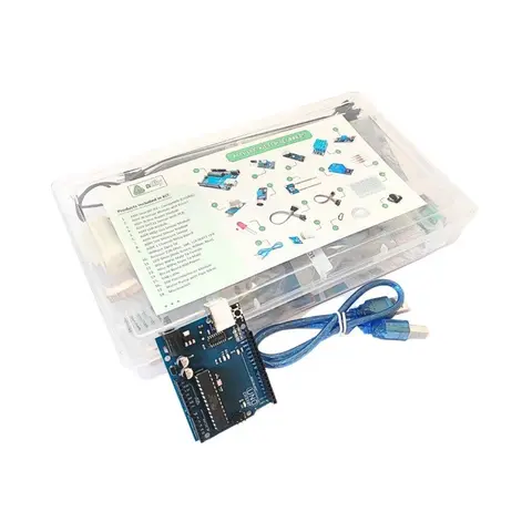
UNO R3 Beginner kit – ADIY
ADIY Uno R3 Beginners Kit is a Stepping Stone for beginners who want to learn about electronic sensors and are excited to make projects. Beginners can learn the basics of UNO programming. Great for Starting with Arduino…
₹1,469
Datasheet
Share