Sensorsadvancedcomponent deep dive
MQ7 and MQ9 Carbon Monoxide: Heater Cycling Done Properly
Why the MQ7 and MQ9 need a two-phase heater cycle, how to build the 5 V and 1.4 V phases, when to sample, and the real limits of CO sensing.
By ADIY13 min read
Technical review pending. Figures marked “verify” or “check your part” have not been confirmed against your exact hardware revision. Check the manufacturer datasheet before relying on them in a design.
The MQ7 is not a sensor you can read. It is a sensor you have to operate, on a two-phase heater cycle, sampling only in one specific window. Nearly every tutorial online skips this entirely and reads the analog pin in a loop. Those readings are not carbon monoxide measurements.
1. Why this sensor is different#
Our general MQ calibration guide covers the model that applies to the whole family: a heated tin dioxide surface whose resistance falls in the presence of reducing gases, with concentration derived from the ratio Rs/Ro through a power law. All of that still applies here.
What is different about the MQ7 and MQ9 is how you have to run the heater, and it comes down to an awkward physical fact.
The solution the manufacturer arrived at is a cycle. Periodically run the heater hot, which burns the accumulated contaminants off and resets the surface. Then drop to the low temperature, let it settle, and take your reading before contamination builds again.
2. The cycle timings#
| Phase | Heater voltage | Duration | Purpose | Status |
|---|---|---|---|---|
| High (clean) | 5.0 V | 60 s | Burn off adsorbed contaminants | Datasheet (source stated) |
| Low (measure) | approx. 1.4 to 1.5 V | 90 s | CO detection; sample at the end | Datasheet (source stated) |
| Full cycle | — | 150 s | One reading per cycle | Derived (source stated) |
MQ9 differences#
The MQ9 also uses a cycled heater and is sensitive to both carbon monoxide and combustible gases such as methane and LPG, detecting different targets in different phases of its cycle. The principle is the same but the specific voltages, durations and which gas is detected when differ from the MQ7. Read the MQ9 datasheet directly rather than assuming the MQ7 numbers transfer.
3. Driving the heater in hardware#
You now need to produce two different voltages on the heater, under firmware control. There are three sensible approaches.
| Approach | How | Trade-off |
|---|---|---|
| Two switched rails | A 5 V rail and a low voltage rail, each switched by a MOSFET, never both on together. | Most predictable. Highest part count. Recommended for anything serious. |
| Series resistor | 5 V through a MOSFET directly, or through a series resistor that drops it to the low value. | Simple and cheap. The dropped voltage depends on the heater's resistance, which varies with temperature, so the low phase voltage is approximate. |
| PWM through a MOSFET | Switch 5 V at high frequency, let the heater's thermal mass average it. | Fewest parts. But you are controlling average power, not voltage, and must verify the resulting temperature rather than assuming duty cycle maps to the datasheet voltage. |
4. Firmware#
/*
 * ADIY Labs — MQ7 dual-phase heater cycle
 *
 * Implements the datasheet cycle: 5 V for 60 s (clean),
 * then low voltage for 90 s (measure), sampling at the END
 * of the low phase.
 *
 * HARDWARE ASSUMED:
 *   HEATER_HIGH_PIN -> MOSFET gate switching the 5 V rail
 *   HEATER_LOW_PIN  -> MOSFET gate switching the low rail
 *   MQ_ANALOG_PIN   -> sensor output divider
 *   The two rails must NEVER be on simultaneously.
 *
 * Non-blocking: uses millis(), so your main loop keeps running.
 * A blocking delay() implementation would stall everything else
 * for two and a half minutes at a time.
 *
 * NOT bench-verified in this revision. Verify against your own
 * datasheet and hardware before relying on it.
 */
#define HEATER_HIGH_PIN   5
#define HEATER_LOW_PIN    6
#define MQ_ANALOG_PIN     A0
// Datasheet cycle. Check against YOUR datasheet revision.
#define HIGH_PHASE_MS     60000UL    // 60 s at 5.0 V
#define LOW_PHASE_MS      90000UL    // 90 s at ~1.4 V
// Sample during the final 2 s of the low phase, when the
// surface has settled and before the cycle restarts.
#define SAMPLE_WINDOW_MS  2000UL
// Ro from YOUR clean-air calibration. See our MQ calibration
// article. This placeholder is NOT a usable value.
#define RO_KOHM           10.0
#define RL_KOHM           10.0      // MEASURE your board's load resistor
#define VC                5.0
#define ADC_MAX           1023.0
enum Phase { PHASE_HIGH, PHASE_LOW };
Phase    phase        = PHASE_HIGH;
uint32_t phaseStart   = 0;
uint32_t sampleSum    = 0;
uint32_t sampleCount  = 0;
float    lastRatio    = -1;
// Both rails off, then the requested one on. Order matters:
// never allow an instant where both are driven.
void setHeater(Phase p) {
  digitalWrite(HEATER_HIGH_PIN, LOW);
  digitalWrite(HEATER_LOW_PIN,  LOW);
  delayMicroseconds(100);             // break-before-make
  if (p == PHASE_HIGH) digitalWrite(HEATER_HIGH_PIN, HIGH);
  else                 digitalWrite(HEATER_LOW_PIN,  HIGH);
}
float adcToRs(float adc) {
  float vout = adc * VC / ADC_MAX;
  if (vout < 0.01) return -1.0;      // disconnected?
  return RL_KOHM * (VC - vout) / vout;
}
void setup() {
  Serial.begin(115200);
  // Set levels before making outputs, so we do not glitch
  // both rails on at boot.
  digitalWrite(HEATER_HIGH_PIN, LOW);
  digitalWrite(HEATER_LOW_PIN,  LOW);
  pinMode(HEATER_HIGH_PIN, OUTPUT);
  pinMode(HEATER_LOW_PIN,  OUTPUT);
  Serial.println("MQ7 heater cycle starting.");
  Serial.println("First valid reading in ~150 s.");
  Serial.println("New sensors need 24-48 h burn-in first.");
  phase      = PHASE_HIGH;
  phaseStart = millis();
  setHeater(PHASE_HIGH);
}
void loop() {
  uint32_t now     = millis();
  uint32_t elapsed = now - phaseStart;
  if (phase == PHASE_HIGH) {
    // Cleaning. Any ADC reading now is meaningless. Do not log it.
    if (elapsed >= HIGH_PHASE_MS) {
      phase       = PHASE_LOW;
      phaseStart  = now;
      sampleSum   = 0;
      sampleCount = 0;
      setHeater(PHASE_LOW);
    }
  }
  else {   // PHASE_LOW
    // Accumulate only inside the sampling window at the very
    // end of the low phase. Earlier readings are still settling.
    if (elapsed >= (LOW_PHASE_MS - SAMPLE_WINDOW_MS)
        && elapsed < LOW_PHASE_MS) {
      sampleSum += analogRead(MQ_ANALOG_PIN);
      sampleCount++;
    }
    if (elapsed >= LOW_PHASE_MS) {
      if (sampleCount > 0) {
        float adc = (float)sampleSum / sampleCount;
        float rs  = adcToRs(adc);
        if (rs > 0) {
          lastRatio = rs / RO_KOHM;
          // Report the ratio. It is the honest measurement.
          // Converting to ppm requires curve constants read
          // from YOUR datasheet — see our MQ calibration guide.
          Serial.print("Cycle complete. Rs/Ro = ");
          Serial.println(lastRatio, 3);
        } else {
          Serial.println("Sensor fault: output near zero.");
        }
      }
      phase      = PHASE_HIGH;
      phaseStart = now;
      setHeater(PHASE_HIGH);
    }
  }
  // Main loop stays free. Do your other work here.
}
Non-blocking two-phase heater cycle with sampling confined to the end of the low phase.
5. Implementation pitfalls#
| Mistake | Consequence |
|---|---|
| Reading the analog pin continuously | Numbers that respond to breath and mean nothing. The most common error by a wide margin. |
| Sampling at the start of the low phase | Surface still cooling and settling. Reading is not stable. |
| Sampling during the high phase | Completely meaningless. Wrong temperature entirely. |
Using delay() for the phases | Blocks the entire program for 150 s. Nothing else in your device runs. |
| Both heater rails on at once | Shorts one supply into the other. Use break-before-make switching. |
| Driving the heater from a GPIO | Insufficient current. Possible pin damage. |
| Skipping burn-in | A new sensor drifts for a day or more. Any Ro captured early is wrong. |
| Assuming MQ7 timings apply to MQ9 | Different cycle. Read the MQ9 datasheet. |
| Using a breakout with a hard-wired heater | Cannot cycle at all. Check board access before designing firmware. |
6. Honest limits#
Even implemented correctly, be clear about what you have.
- Selectivity is limited. Like the rest of the family, the MQ7 responds to more than one gas. The heater cycle improves CO discrimination considerably compared to running it continuously, but it does not make the sensor specific to carbon monoxide.
- Individual calibration is still required. Everything in our MQ calibration article about per-sensor Ro, verifying the load resistor and deriving curve constants from the datasheet applies equally here. The cycle is additional to that work, not a substitute for it.
- Temperature and humidity affect the reading. Datasheet curves are specified at one condition; deployment is not at that condition.
- Response is slow by design. One reading per 150 s is not suitable for anything needing fast detection.
- Sensors age. Ro drifts over months. Periodic recalibration is required for readings to remain comparable over time.
FAQ#
Why does the MQ7 need a heater voltage cycle?
The sensing surface responds to carbon monoxide only at a relatively low temperature, but at that temperature other gases also adsorb onto the surface and accumulate, progressively poisoning the response. The high temperature phase burns those contaminants off. So the high phase cleans and the low phase measures. Without the cycle the surface saturates and readings drift into meaninglessness.
What are the MQ7 heater cycle timings?
The commonly cited datasheet cycle is 5 V for 60 seconds followed by approximately 1.4 to 1.5 V for 90 seconds, with the measurement taken at the end of the low voltage phase. Sources differ between 1.4 V and 1.5 V; use the value in the datasheet supplied with your sensor.
Can I just read the analog pin continuously like other MQ sensors?
You will get a number, but not a meaningful CO measurement. This is what most published MQ7 tutorials do. Running the heater continuously at 5 V holds the sensor at the wrong temperature for CO detection; running it continuously low lets other gases accumulate. The dual phase cycle is not optional for this part.
Can I drive the MQ7 heater from a PWM pin?
Not directly. The heater draws far more current than a pin can supply, so it needs a transistor or MOSFET regardless. And PWM controls average power rather than voltage, so you must verify the resulting element temperature rather than assuming duty cycle maps to the datasheet voltage. Two switched rails is more predictable.
Is an MQ7 suitable for a carbon monoxide alarm?
No. CO is lethal and undetectable by human senses, and CO alarms are safety-critical devices subject to standards covering response time, fault detection, thresholds and calibration traceability. An MQ7 on a breadboard meets none of those. Use a certified alarm for life safety.
Sources#
Sources and further reading#
- Hanwei Electronics, MQ-7 Semiconductor Sensor for Carbon Monoxide technical data. Source for the dual voltage heater cycle and its timings.
- Hanwei Electronics, MQ-9 Gas Sensor technical data, for the differing MQ9 cycle.
- Published application notes and community implementations of MQ7 heater cycling, consulted for the 1.4 versus 1.5 V discrepancy noted in section 2.
- Our own MQ gas sensor calibration guide for the underlying Rs/Ro model.
Products & resources
- MQ7 Gas Sensor Module Datasheet
- MQ9 Gas Sensor Datasheet
- Humidity and Temperature Sensor – DHT11 Datasheet
- ADIY LM393 Comparator Datasheet
Gas Sensors
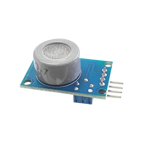
MQ7 Gas Sensor Module – ADIY
ADIY Gas Sensor module MQ7 provides an analog output corresponding to the concentration of the gases in the air and an easy-to-use digital output. The onboard potentiometer can be used to set the maximum gas…
₹125
Datasheet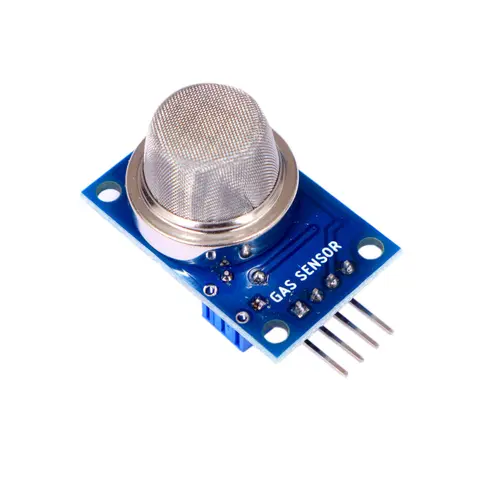
Gas Sensors
MQ9 Gas Sensor Module – ADIY
ADIY – Gas Sensor MQ9 Module is useful for gas leakage detection (in home and industry). It is suitable for detecting LPG, CO, CH4. It provides an analog output corresponding to the concentration of the gases in the air…
₹127
Datasheet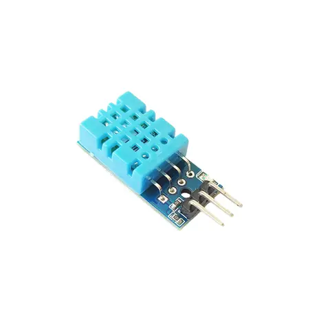
Temperature Sensors
DHT11 Sensor – Humidity and Temperature Sensor
DHT11 Sensor is a versatile and affordable device that accurately measures both humidity and temperature. Ideal for various applications, from smart homes to weather monitoring systems, it provides reliable data for…
₹85
Datasheet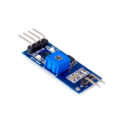
Converter Boards
LM393 Comparator Module – ADIY
The comparator LM393 module is used to digitize any resistive sensor. The module produces an output voltage according to the resistance of the connected sensor and is made available at the Analog Output (AO) pin. The…
₹33
Datasheet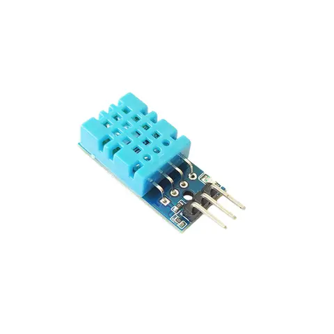
Temperature Sensors
ADIY DHT11 Sensor Module
This is a very popular, ultra-low cost digital temperature and humidity sensor. It uses a capacitive humidity sensor, and a thermistor to measure the surrounding air temperature. The result is available via a digital…
₹65
Share