Interfacing & Displaysbeginneradiy labs
SSD1306 OLED Display with Arduino & ESP32: Wiring, Libraries & Graphics Tutorial
Use the 0.96 inch SSD1306 I2C OLED with Arduino and ESP32: wiring, Adafruit libraries, text, graphics, bitmaps and troubleshooting.
By ADIY12 min read
Technical review pending. Figures marked “verify” or “check your part” have not been confirmed against your exact hardware revision. Check the manufacturer datasheet before relying on them in a design.
1. Introduction — Why OLED Displays are Perfect for Embedded Projects#
If you're building an embedded project, you likely need a way to present data visually. While standard 16x2 LCDs are great for simple character displays, they are bulky and limited in terms of graphical capabilities. This is where the 0.96" SSD1306 OLED display shines.
OLED stands for Organic Light-Emitting Diode. Unlike LCDs, which require a backlight, each individual pixel on an OLED panel emits its own light. This results in stunning contrast, incredibly deep blacks, excellent viewing angles, and a very crisp picture. Furthermore, OLED displays consume very little power because pixels that are black are completely turned off.
In this comprehensive guide, we will dive deep into using the 0.96-inch SSD1306 I2C OLED display. We'll explore how to wire it up with both the classic ADIY UNO R3 and the powerful ESP32. We will cover the installation of necessary libraries, displaying basic text, drawing complex geometric shapes, loading custom bitmap images, and even creating a live sensor dashboard.
2. SSD1306 OLED Specs: 0.96" vs 1.3", I2C vs SPI#
Before writing code, it's crucial to understand the hardware. The SSD1306 is merely the controller chip embedded inside the display. The displays themselves come in a few variations:
- Size: The most common sizes are 0.96-inch and 1.3-inch. The 0.96" usually uses the SSD1306 driver, while some 1.3" models use the SH1106 driver (which requires a slightly different library).
- Resolution: The standard resolution is 128x64 pixels, though 128x32 variants also exist.
- Color: Most are monochrome (white or blue pixels), though some have the top 16 rows colored yellow and the bottom 48 rows blue.
- Operating Voltage: These displays typically run on 3.3V to 5V, making them seamlessly compatible with both 5V Arduino boards and 3.3V boards like the ESP32 or Raspberry Pi Pico.
3. I2C vs SPI Comparison Table#
OLED modules are generally available in two communication protocols: I2C (Inter-Integrated Circuit) and SPI (Serial Peripheral Interface). If you have a choice, which one should you pick? Here is a breakdown:
| Feature | I2C OLED (4 Pins) | SPI OLED (7 Pins) |
|---|---|---|
| Wiring Complexity | Low (only 4 wires needed) | High (requires 7 wires) |
| Data Speed | Standard (up to 400 kHz), fine for text | Fast (up to 10 MHz), best for animations |
| Pin Usage | Only 2 IO pins (SDA, SCL) | Uses 5 IO pins (MOSI, CLK, DC, CS, RES) |
| Addressing | Requires an I2C address (usually 0x3C) | Uses Chip Select (CS) pin for addressing |
| Best For | General projects, sensor dashboards, limited pins | High frame-rate graphics, gaming, fast updates |
In this tutorial, we are focusing on the I2C OLED, as it is the most popular and easiest to interface for beginners.
4. Wiring: 0.96" I2C OLED with ADIY UNO R3#
Connecting the I2C OLED to an Arduino (like the ADIY UNO R3) is incredibly straightforward. You only need four jumper wires. The display can be powered safely from the Arduino's 5V pin.
| OLED Pin | Arduino UNO / ADIY UNO R3 Pin | Description |
|---|---|---|
| VCC | 5V | Power supply |
| GND | GND | Ground connection |
| SCL | A5 (or dedicated SCL) | I2C Clock line |
| SDA | A4 (or dedicated SDA) | I2C Data line |
5. Wiring: OLED with ESP32#
The ESP32 is a 3.3V logic microcontroller. The OLED is completely compatible with 3.3V. The default I2C pins on most ESP32 development boards are GPIO21 for SDA and GPIO22 for SCL.
| OLED Pin | ESP32 Pin | Description |
|---|---|---|
| VCC | 3V3 | 3.3V Power supply |
| GND | GND | Ground connection |
| SCL | GPIO22 | I2C Clock line |
| SDA | GPIO21 | I2C Data line |
6. Installing Adafruit SSD1306 Library#
To communicate with the OLED display effortlessly, we will use the highly reliable libraries provided by Adafruit. We need two libraries: one specific to the SSD1306 hardware, and the core graphics library.
Follow these steps in your Arduino IDE:
- Open the Arduino IDE and go to Sketch > Include Library > Manage Libraries...
- In the search bar, type
Adafruit SSD1306. - Find the one by Adafruit and click Install.
- Next, search for
Adafruit GFX Library. - Install this library as well. (If the IDE prompts you to install missing dependencies for either library, select "Install All").
7. Code 1: Display Text (Hello World, Sizes, Positioning)#
Let's start with the basics: printing text on the screen. The Adafruit GFX library provides functions to set text size, color, and cursor position. Remember that the screen origin (0,0) is at the top-left corner.
#include <Wire.h>
#include <Adafruit_GFX.h>
#include <Adafruit_SSD1306.h>
#define SCREEN_WIDTH 128 // OLED display width, in pixels
#define SCREEN_HEIGHT 64 // OLED display height, in pixels
// Declaration for an SSD1306 display connected to I2C (SDA, SCL pins)
// The pins for I2C are defined by the Wire-library.
#define OLED_RESET     -1 // Reset pin # (or -1 if sharing Arduino reset pin)
#define SCREEN_ADDRESS 0x3C // See datasheet for Address; 0x3D for 128x64, 0x3C for 128x32
Adafruit_SSD1306 display(SCREEN_WIDTH, SCREEN_HEIGHT, &Wire, OLED_RESET);
void setup() {
  Serial.begin(115200);
  // SSD1306_SWITCHCAPVCC = generate display voltage from 3.3V internally
  if(!display.begin(SSD1306_SWITCHCAPVCC, SCREEN_ADDRESS)) {
    Serial.println(F("SSD1306 allocation failed"));
    for(;;); // Don't proceed, loop forever
  }
  // Clear the buffer
  display.clearDisplay();
  // Set text properties
  display.setTextSize(1);      // Normal 1:1 pixel scale
  display.setTextColor(SSD1306_WHITE); // Draw white text

  display.setCursor(0, 0);     // Start at top-left corner
  display.println(F("Hello, ADIY!"));

  display.setTextSize(2);      // 2X scale
  display.setCursor(0, 20);
  display.println(F("Make in"));

  display.setTextSize(3);      // 3X scale
  display.setCursor(0, 40);
  display.println(F("India"));
  // Show the display buffer on the screen. You MUST call display() after
  // drawing commands to make them visible on screen!
  display.display();
}
void loop() {
  // Nothing to do here
}
Code Explanation: We initialize the display using display.begin(). The I2C address is usually 0x3C, but if yours doesn't work, try 0x3D. After setting up, we use clearDisplay() to wipe the screen memory buffer. setTextSize() adjusts the font multiplier, and setCursor(x, y) moves the printing point. Finally, display.display() pushes the buffer from the Arduino's RAM to the OLED hardware.
8. Code 2: Draw Shapes (Lines, Rectangles, Circles)#
Because the OLED is a graphic display (unlike an LCD character display), we can address individual pixels. The Adafruit GFX library makes it easy to draw geometric shapes.
#include <Wire.h>
#include <Adafruit_GFX.h>
#include <Adafruit_SSD1306.h>
#define SCREEN_WIDTH 128
#define SCREEN_HEIGHT 64
#define OLED_RESET -1
#define SCREEN_ADDRESS 0x3C
Adafruit_SSD1306 display(SCREEN_WIDTH, SCREEN_HEIGHT, &Wire, OLED_RESET);
void setup() {
  display.begin(SSD1306_SWITCHCAPVCC, SCREEN_ADDRESS);
  display.clearDisplay();
  // 1. Draw a single line (x0, y0, x1, y1, color)
  display.drawLine(0, 0, 127, 63, SSD1306_WHITE);

  // 2. Draw a rectangle (x, y, width, height, color)
  display.drawRect(10, 10, 40, 20, SSD1306_WHITE);

  // 3. Draw a filled rectangle (x, y, width, height, color)
  display.fillRect(60, 10, 40, 20, SSD1306_WHITE);

  // 4. Draw a circle (x_center, y_center, radius, color)
  display.drawCircle(30, 45, 10, SSD1306_WHITE);

  // 5. Draw a filled circle (x_center, y_center, radius, color)
  display.fillCircle(80, 45, 10, SSD1306_WHITE);
  // Push to screen
  display.display();
}
void loop() {}
9. Code 3: Display Bitmap Image#
Displaying logos or icons is a great way to make your project look professional. To display an image on an OLED, you must first convert a black-and-white image into a C-style array (hexadecimal data). You can use tools like LCD Image Converter or online generators like image2cpp.
Below is an example of displaying a small 32x32 pixel heart icon:
#include <Wire.h>
#include <Adafruit_GFX.h>
#include <Adafruit_SSD1306.h>
#define SCREEN_WIDTH 128
#define SCREEN_HEIGHT 64
#define OLED_RESET -1
Adafruit_SSD1306 display(SCREEN_WIDTH, SCREEN_HEIGHT, &Wire, OLED_RESET);
// 'heart_icon', 32x32px
const unsigned char epd_bitmap_heart_icon [] PROGMEM = {
  0x00, 0x00, 0x00, 0x00, 0x00, 0x00, 0x00, 0x00, 0x00, 0x00, 0x00, 0x00, 0x00, 0x7e, 0x7e, 0x00,
  0x03, 0xff, 0xff, 0xc0, 0x07, 0xff, 0xff, 0xe0, 0x0f, 0xff, 0xff, 0xf0, 0x1f, 0xff, 0xff, 0xf8,
  0x3f, 0xff, 0xff, 0xfc, 0x3f, 0xff, 0xff, 0xfc, 0x7f, 0xff, 0xff, 0xfe, 0x7f, 0xff, 0xff, 0xfe,
  0x7f, 0xff, 0xff, 0xfe, 0x7f, 0xff, 0xff, 0xfe, 0x3f, 0xff, 0xff, 0xfc, 0x3f, 0xff, 0xff, 0xfc,
  0x1f, 0xff, 0xff, 0xf8, 0x0f, 0xff, 0xff, 0xf0, 0x07, 0xff, 0xff, 0xe0, 0x03, 0xff, 0xff, 0xc0,
  0x01, 0xff, 0xff, 0x80, 0x00, 0xff, 0xff, 0x00, 0x00, 0x7f, 0xfe, 0x00, 0x00, 0x3f, 0xfc, 0x00,
  0x00, 0x1f, 0xf8, 0x00, 0x00, 0x0f, 0xf0, 0x00, 0x00, 0x07, 0xe0, 0x00, 0x00, 0x03, 0xc0, 0x00,
  0x00, 0x01, 0x80, 0x00, 0x00, 0x00, 0x00, 0x00, 0x00, 0x00, 0x00, 0x00, 0x00, 0x00, 0x00, 0x00
};
void setup() {
  display.begin(SSD1306_SWITCHCAPVCC, 0x3C);
  display.clearDisplay();
  // drawBitmap(x, y, bitmap_array, width, height, color)
  display.drawBitmap(48, 16, epd_bitmap_heart_icon, 32, 32, SSD1306_WHITE);
  display.display();
}
void loop() {}10. Code 4: Sensor Dashboard (Show DHT22 Data Live)#
One of the best use cases for an OLED display is building a live dashboard for sensor data. In this example, we combine a DHT22 temperature and humidity sensor with our display. (Don't have a DHT22? Check out our DHT11/DHT22 guide here).
You will need to install the DHT sensor library by Adafruit.
#include <Wire.h>
#include <Adafruit_GFX.h>
#include <Adafruit_SSD1306.h>
#include "DHT.h"
#define SCREEN_WIDTH 128
#define SCREEN_HEIGHT 64
Adafruit_SSD1306 display(SCREEN_WIDTH, SCREEN_HEIGHT, &Wire, -1);
#define DHTPIN 2       // Digital pin connected to the DHT sensor
#define DHTTYPE DHT22  // DHT 22 (AM2302)
DHT dht(DHTPIN, DHTTYPE);
void setup() {
  display.begin(SSD1306_SWITCHCAPVCC, 0x3C);
  dht.begin();

  display.clearDisplay();
  display.setTextColor(SSD1306_WHITE);
}
void loop() {
  // Read humidity and temp
  float h = dht.readHumidity();
  float t = dht.readTemperature();
  display.clearDisplay();

  // Header
  display.setTextSize(1);
  display.setCursor(0,0);
  display.print("Environment Monitor");
  display.drawLine(0, 10, 128, 10, SSD1306_WHITE);
  // Print Temperature
  display.setTextSize(2);
  display.setCursor(0, 20);
  display.print("T: ");
  display.print(t, 1);
  display.print(" C");
  // Print Humidity
  display.setCursor(0, 45);
  display.print("H: ");
  display.print(h, 1);
  display.print(" %");
  display.display(); // Update screen
  delay(2000); // DHT needs 2 seconds between readings
}11. Code 5: Scrolling Text Animation#
The SSD1306 hardware has built-in capability to scroll the screen horizontally or diagonally without tying up the Arduino processor! Here is how you trigger the hardware scroll.
#include <Wire.h>
#include <Adafruit_GFX.h>
#include <Adafruit_SSD1306.h>
Adafruit_SSD1306 display(128, 64, &Wire, -1);
void setup() {
  display.begin(SSD1306_SWITCHCAPVCC, 0x3C);

  display.clearDisplay();
  display.setTextSize(2);
  display.setTextColor(SSD1306_WHITE);
  display.setCursor(10, 25);
  display.println("SCROLLING!");
  display.display();
  delay(1000);

  // Scroll entire screen to the right
  display.startscrollright(0x00, 0x0F);
  delay(4000);

  // Stop scrolling
  display.stopscroll();
  delay(1000);

  // Scroll entire screen to the left
  display.startscrollleft(0x00, 0x0F);
  delay(4000);

  display.stopscroll();
}
void loop() {}
12. Troubleshooting Common OLED Issues#
Working with OLEDs can sometimes be frustrating if you encounter a blank screen. Here is a checklist of common problems and their solutions:
- Screen Remains Completely Blank:
- Wrong I2C Address: Most tutorials assume
0x3C, but some boards (especially 1.3" models or specific batches) use0x3D. Run an I2C Scanner sketch to find your exact address. - Swapped SDA/SCL: It is incredibly easy to plug the SDA wire into SCL and vice versa. Double-check your wiring against the table in Section 4.
- Forgot display.display(): A very common coding error. The display will stay blank until you call
display.display()to push the buffer.
- Wrong I2C Address: Most tutorials assume
- Garbage or Random Pixels on Screen: This usually means the Arduino is running out of SRAM. The 128x64 display buffer requires 1024 bytes (1KB) of RAM. Since the UNO only has 2KB total, large code structures or multiple libraries will cause a crash. Consider moving to an ESP32 or reducing text usage.
- Screen shifts or shows weird lines: You might be using a 128x64 library definition for a 128x32 screen, or you might actually have an SH1106 display (common for 1.3" sizes). If the Adafruit SSD1306 library produces shifted pixels, switch to the
U8g2library or an SH1106 specific library.
13. Frequently Asked Questions#
Why is my 0.96 OLED display blank?
The most common reason for a blank OLED is using the wrong I2C address. Check if your display uses 0x3C or 0x3D by running an I2C scanner sketch. Additionally, check wiring and make sure SCL and SDA are not swapped.
Can I use the SSD1306 OLED display with ESP32?
Yes! The SSD1306 OLED is fully compatible with ESP32. Just wire the I2C pins to ESP32's default GPIO22 (SCL) and GPIO21 (SDA) and power it via 3.3V, as ESP32 is a 3.3V logic board.
What is the difference between I2C and SPI OLED displays?
I2C displays only require 4 wires (VCC, GND, SDA, SCL) and are easier to connect, but they are slightly slower to refresh. SPI displays require 7 wires, occupy more pins on the microcontroller, but offer faster refresh rates for complex animations.
How do I display custom images on the OLED?
You can convert a monochrome image to a C byte array using software like LCD Image Converter or online tools. Then, use the drawBitmap() function from the Adafruit GFX library to render the array on the screen.
Products & resources
Arduino Compatible
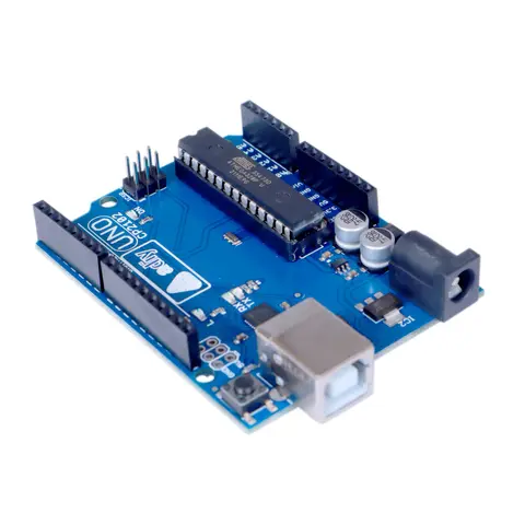
Uno R3 – Compatible CP2102
The ADIY Uno R3 CP2102 ATmega328P Development Board is a cost-effective alternative to the popular Arduino Uno R3. It is designed for beginners and professionals alike, offering robust performance and reliability. Key…
₹552
Datasheet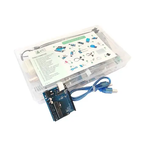
Arduino Compatible
UNO R3 Beginner kit – ADIY
ADIY Uno R3 Beginners Kit is a Stepping Stone for beginners who want to learn about electronic sensors and are excited to make projects. Beginners can learn the basics of UNO programming. Great for Starting with Arduino…
₹1,469
Datasheet
Share